2 Wire Speed Sensor Wiring Diagram. Be careful not to cut the hole too large. Now about your question you can't determine exact voltage level of signal.
gm 2 wire speed sensor wiring diagram CaoilfhinFox from caoilfhinfox.blogspot.com
Hole in the firewall for the speedometer wires. 8mount speedometer in a 33/ dia. Web as the vehicle speed increases, the sensor produces a higher frequency signal the vehicle speed sensor (vss) supplies this signal to the components that.
Web As The Vehicle Speed Increases, The Sensor Produces A Higher Frequency Signal The Vehicle Speed Sensor (Vss) Supplies This Signal To The Components That.
Web normally most of speed sensor have 3 wire 1. Now about your question you can't determine exact voltage level of signal. This type of diagram depicts two wires that are connected to.
Web The Most Common Connection Is As Follows:
8cut a 3/ dia. Web as the name implies, an sd sensor uses three wires to allow for more accurate readings, including a voltage wire, a ground wire, and a data wire. 8mount speedometer in a 33/ dia.
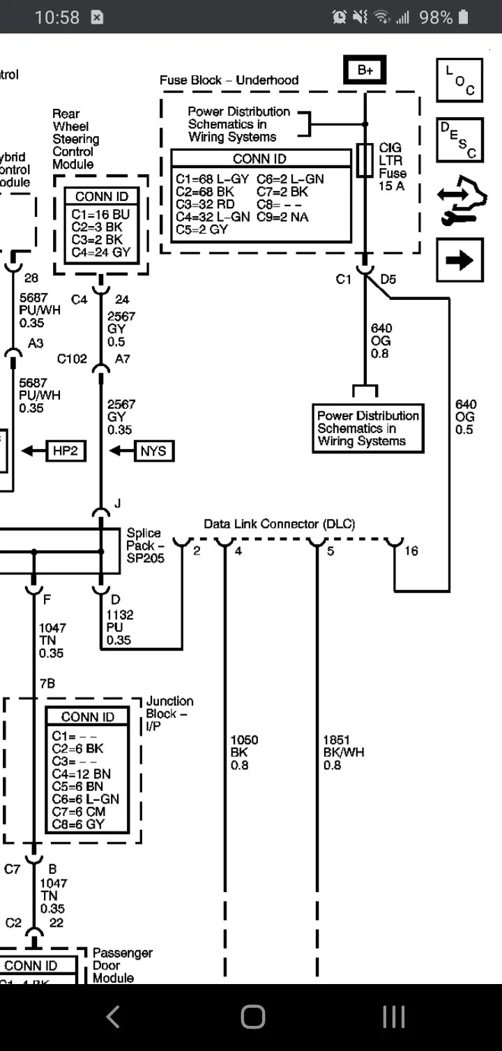
Web The Diagram Below Shows The Typical Wiring For These Sensors.
Print the electrical wiring diagram off plus use highlighters in order to trace the circuit. Hole in the firewall for the speedometer wires. Whilst 1 wire sensors will work, they are.
Place A Rubber Grommet In The.
Be careful not to cut the hole too large. Web in the wiring diagrams below you will notice the different call outs for the polarized vs. Use of 2 wire temperature sensors is highly recommended.